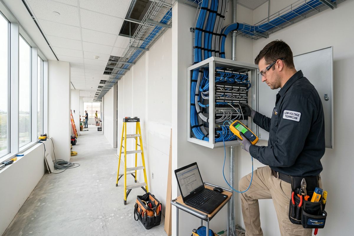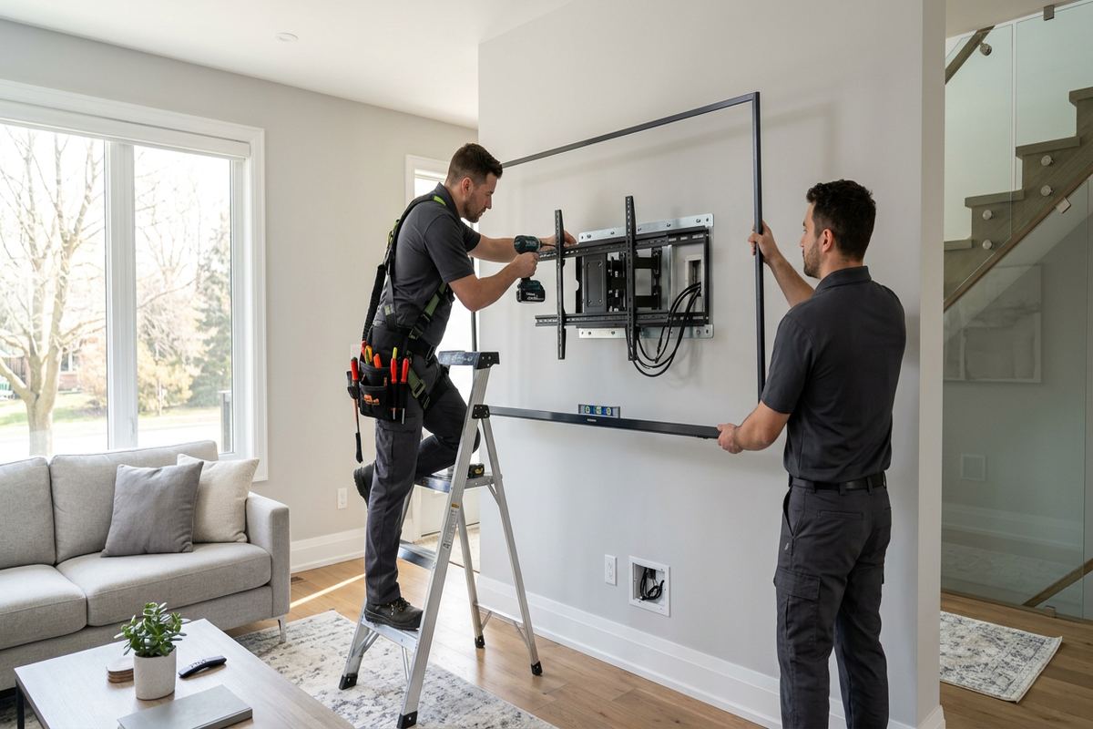
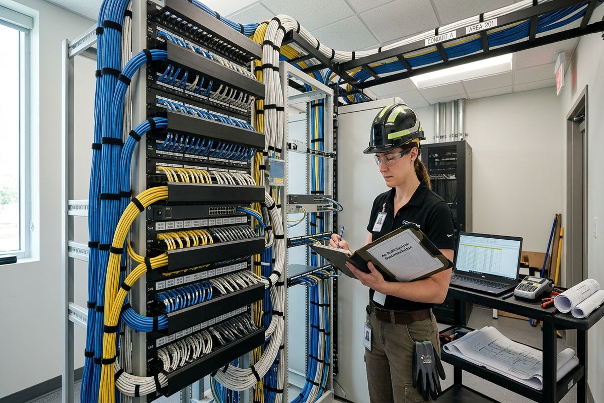
UnifiedLink designs coordinated low-voltage systems for homes, commercial spaces and industrial units in Burlington. Planning covers device locations, cable routes, equipment spaces, network capacity, power requirements and future expansion. A site assessment comes before pricing, followed by a written scope that installers, owners and other trades can use throughout the project.
Low-Voltage Planning for Burlington Properties
A complete design brings security cameras, alarms, access control, structured cabling, Wi-Fi, audio and displays into one coordinated plan. Instead of treating each system as a separate purchase, UnifiedLink considers how devices share pathways, network switches, equipment racks, internet service and backup power. This helps prevent duplicated cable, crowded utility areas and devices placed without regard for coverage or maintenance. For Burlington owners, the result is a practical reference for construction, renovation or phased installation, with decisions made before finished walls and ceilings restrict access.
Burlington’s varied property types require different design approaches. Lakefront homes may need careful exterior device placement and sealing because exposed elevations face moisture, wind and repeated freeze-thaw conditions. Mid-century bungalows often have limited service spaces, finished basements and framing layouts that affect cable routes. Small commercial plazas introduce shared walls, suspended ceilings, landlord requirements and multiple tenant services. The design records these constraints early, allowing routes and mounting methods to suit the actual building rather than relying on assumptions made from a floor plan alone.
Work begins with a site assessment before pricing. Existing construction, proposed renovations, available pathways, electrical locations, internet entry points and equipment spaces are reviewed. We discuss how each room or work area will be used, which systems are needed now and what may be added later. The resulting written scope covers equipment, cable routes, device placement, exclusions, equipment ownership and warranty. This gives the property owner, contractor and other trades a common description of the work and reduces uncertainty when installation begins.
- Site use and system requirements review
- Existing pathway and equipment-space assessment
- Device locations coordinated before installation
- Written scope prepared before work proceeds
Designing Around Burlington Building Stock
Construction methods strongly influence low-voltage design. In frame houses, routes may follow joist spaces, attic areas or accessible wall cavities, although insulation and finished basements can limit those options. Masonry walls often require surface pathways, carefully selected penetrations or routes through adjacent framed partitions. In neighbourhoods such as Roseland and Aldershot, additions and renovations can create several construction types within one property. A site-based design identifies these transitions and specifies realistic cable paths without assuming that every wall or ceiling can be opened.
Mid-century bungalows commonly place utilities in basements that have since been divided or finished. An equipment location that appears convenient may lack ventilation, working clearance or a suitable route to upper-floor devices. The design therefore considers rack depth, patching access, heat from active equipment and the ability to replace components without disturbing finished rooms. Where a renovation is planned, cable installation can be coordinated with demolition and drywall work. Where finishes will remain, routes are selected to limit disruption while preserving serviceability and continuous cable runs.
Newer homes in Alton Village or Orchard may have existing communications panels and builder-installed cabling, but those provisions still need to be verified. Cable category, termination quality, labelling, pathway capacity and outlet placement can vary from what a new owner’s systems require. The design can incorporate usable infrastructure, identify cables that should be tested and plan additions where coverage or capacity is insufficient. This avoids replacing functional work unnecessarily while ensuring that cameras, wireless access points, televisions and networked controls connect through an organized, documented layout.
- Frame and masonry routes assessed separately
- Finished areas considered before selecting pathways
- Existing builder cabling reviewed for reuse
- Equipment access and ventilation included
Coordinating Security, Network and Building Systems
Security and network systems affect one another, so their requirements should be resolved together. Cameras depend on suitable fields of view, mounting surfaces, cable distance, network capacity and recording storage. Access control may require door hardware coordination, power supplies, request-to-exit devices and fire or life-safety interfaces handled by the appropriate trades. Alarm devices need logical coverage without conflicting with air movement or normal occupancy. A coordinated design maps these relationships and identifies responsibilities before separate installers create incompatible pathways or compete for the same equipment space.
Wi-Fi design starts with how the property is built and occupied, not simply with the number of access points. Masonry, mirrors, metal ductwork, concrete floors and neighbouring networks can affect radio performance. In a Millcroft home, coverage may need to extend across several levels and an outdoor living area. In a commercial plaza, tenant separation and denser device use may be more important. Proposed access-point locations are tied to structured cabling and power availability, while network capacity is planned around current applications and reasonable expansion.
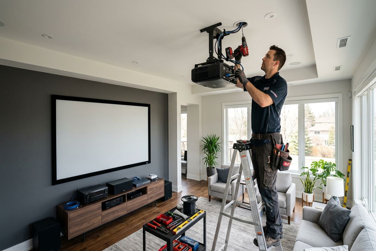
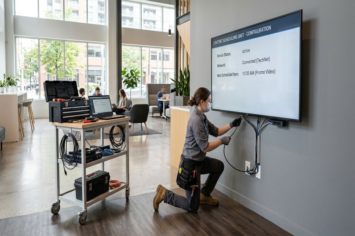
Audio, displays and control devices also need early coordination. Television locations influence conduit, data outlets, mounting reinforcement and equipment storage. Distributed audio requires speaker placement that accounts for room shape, ceiling construction and expected listening areas. Meeting-room displays may need connections for user devices, conferencing equipment and network management. Rather than leaving loose cables behind a screen, the design defines endpoint connections and accessible service points. Shared rack components are organized alongside network and security hardware so that later troubleshooting does not depend on tracing unidentified wiring.
- Camera views and network demand coordinated
- Door hardware responsibilities identified early
- Wi-Fi locations tied to wired backhaul
- Display and audio connections documented
Burlington, Ontario
Low-voltage system design in Burlington, scoped in writing first
Book a site assessment and get equipment, routes, exclusions, and warranty on paper before anything is installed.
Exterior Low-Voltage Design in Burlington
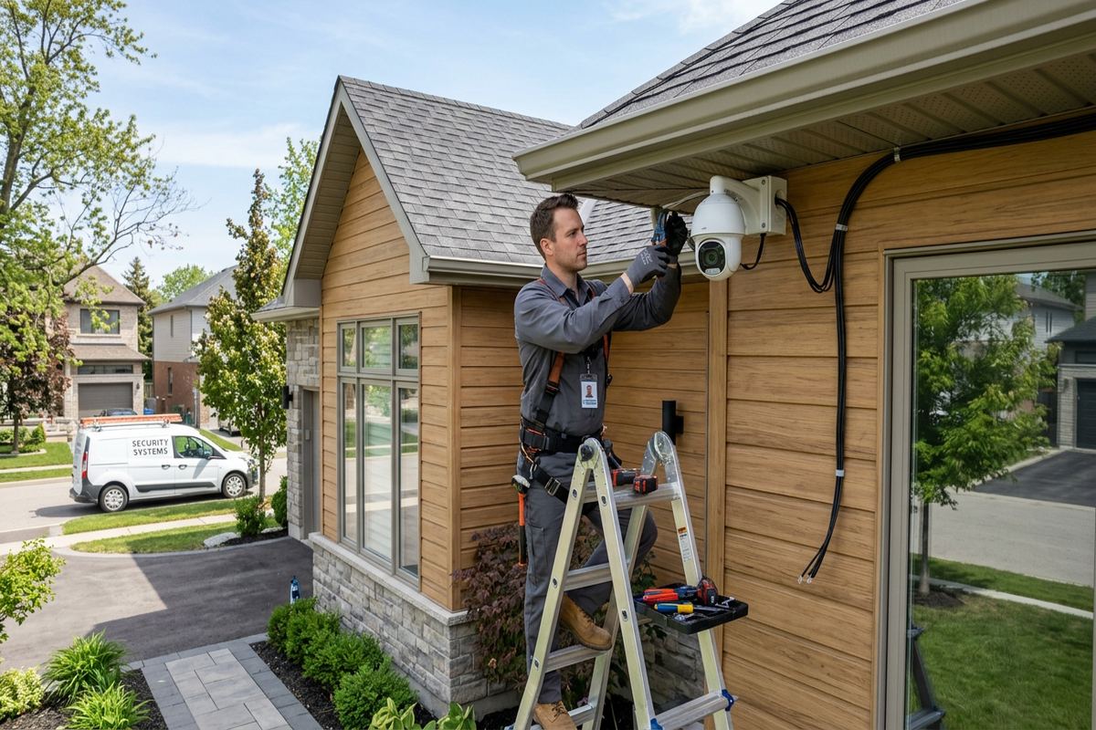
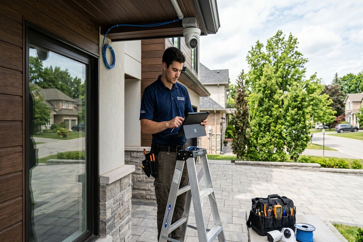
Exterior devices in Burlington must be planned for seasonal exposure. Cameras, wireless equipment, door stations and gate interfaces encounter rain, snow, ice, summer heat and repeated freeze-thaw cycles. Mounting orientation should limit direct water entry, while penetrations require compatible sealing methods that do not trap moisture inside the wall assembly. The design identifies suitable mounting surfaces, cable transitions and accessible junction points. It also avoids casual routing along gutters, loose siding edges or other locations where movement, drainage and maintenance can damage cabling over time.
Lakefront properties can present additional exposure to wind-driven moisture and open sightlines. Camera placement should balance useful identification views with privacy, glare and the appearance of the façade. Infrared reflection from soffits, nearby walls or glass can reduce night image quality, while low mounts may be vulnerable to snow accumulation or tampering. Equipment should remain reachable for maintenance without depending on unsafe access. These factors are reviewed before choosing exact device models or drilling through finished masonry, stucco, siding or trim.
Masonry and frame exteriors need different fastening and penetration details. Brick veneer is not treated as though it were solid structural masonry, and penetrations should account for drainage cavities and interior finishes. On frame walls, device loads and cable entries may need backing or purpose-made mounting blocks. Conduit can be appropriate where concealed routes are unavailable, particularly around commercial strips and industrial units. Its path, supports, transitions and entry fittings should be designed as part of the installation rather than improvised after devices arrive on site.
- Freeze-thaw exposure considered in mounting plans
- Exterior penetrations receive compatible sealing details
- Night views checked for reflective surfaces
- Conduit routes planned where concealment is impractical
Renovations, Condos and Approval Requirements
Renovation design should align low-voltage work with the construction schedule. Cable pathways are easiest to establish after selective demolition but before insulation, drywall and millwork close access. Device heights must be coordinated with cabinetry, lighting, trim and furniture rather than taken from an isolated technology drawing. UnifiedLink can define requirements for the general contractor and relevant trades, including pathway sizes, backing locations and equipment-space needs. Clear sequencing reduces the risk of cutting newly finished surfaces or finding that a planned camera, speaker or display conflicts with another building component.
Condo work may require approval from the condominium corporation or property manager before cabling, mounting or drilling begins. Common elements, exterior walls, corridors, ceiling spaces and shared telecommunications rooms are generally not treated as unrestricted owner space. The design can distinguish work inside the unit from work that may affect common property, giving the owner a clearer package for an approval request. Building rules may also restrict work hours, elevator use, contractor access and firestopping procedures, all of which should be confirmed before installation is scheduled.
Tenants in Downtown Burlington or a small commercial plaza should establish who can authorize changes to the premises. A landlord may need to approve penetrations, exterior cameras, door hardware, roof access, conduit and equipment attached to base-building systems. Lease-end restoration requirements can also affect whether routes are concealed or surface mounted. The written scope records known exclusions and ownership of installed equipment. This helps separate tenant equipment from landlord infrastructure and prevents assumptions about who retains cabling, racks, cameras or access-control components after occupancy changes.
- Low-voltage work sequenced with renovations
- Condo common elements identified before drilling
- Landlord approval needs documented
- Equipment ownership stated in the scope
Cable Pathways and Equipment Spaces in Burlington
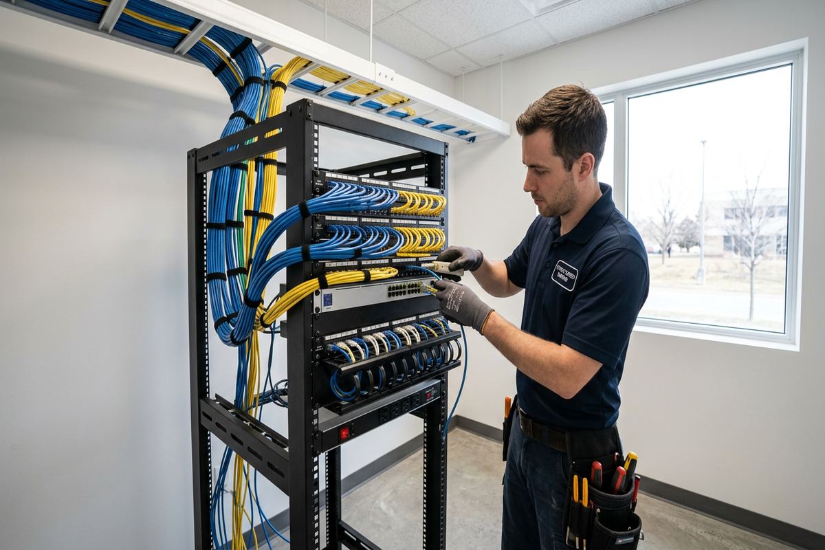
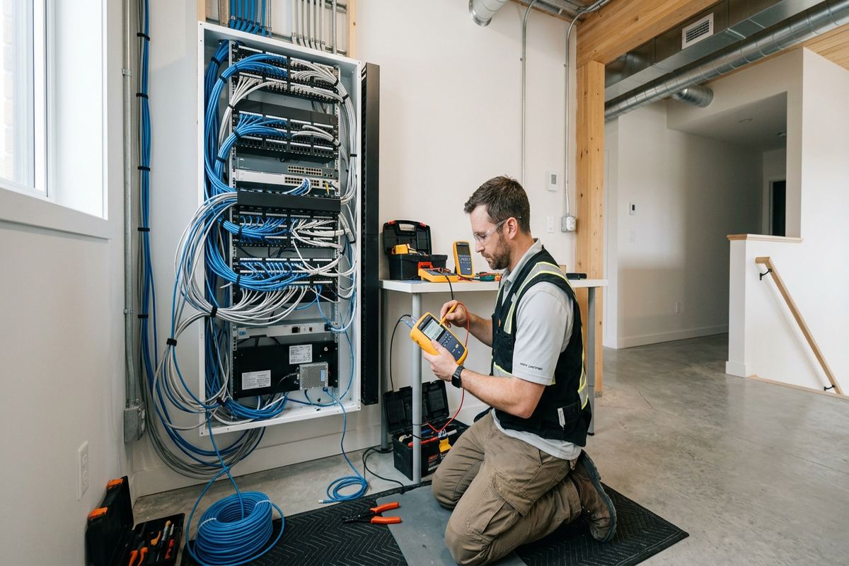
A reliable design gives every cable a defined origin, destination and pathway. Continuous labelled cable runs reduce hidden connection points and make testing or future changes more straightforward. Route selection accounts for cable length, bend radius, separation from electrical conductors and access for installation. In Burlington homes, a central utility room may serve the entire property, but long layouts or detached structures can require another strategy. Commercial suites may need pathways from the landlord’s service area to a tenant rack without crossing inaccessible or unauthorized spaces.
Equipment spaces need more than enough wall area for a small panel. Network switches, recording equipment, alarm hardware, access-control power supplies and audio components may require racks, shelves, patch panels, ventilation and nearby electrical receptacles. Door swing, storage use and working clearance matter because equipment must remain accessible after the room is occupied. The design also considers internet service entry and any demarcation point controlled by a telecommunications provider. Components are arranged so that signal, power and patch cabling can be managed without blocking controls or service access.
Pathway capacity should allow sensible additions without turning every project into an oversized installation. Spare conduit, pull strings or reserved rack space may be useful where future devices are foreseeable and access will later be difficult. In Tyandaga homes undergoing major renovations, planning a route between floors can support future cameras, access points or controls. In industrial units, pathways may need to avoid high-voltage equipment, moving machinery or wet areas. Expansion provisions are documented, but they remain tied to realistic uses rather than unspecified promises of unlimited capacity.
- Continuous labelled runs specified
- Cable separation and bend limits considered
- Rack access and ventilation planned
- Practical expansion pathways documented
From Site Assessment to Installation
Design decisions are confirmed against site conditions before a final scope is issued. The assessment may include measuring routes, reviewing accessible ceiling or attic areas, checking proposed device views and identifying construction that limits concealed cabling. Drawings supplied by an owner or contractor are useful, but they do not replace field verification in an existing building. Site assessment timing depends on the service and travel distance. Requests sent during business hours are answered the same day, while after-hours requests are answered the next business day.
The written scope turns observations into defined work. It covers equipment, cable routes, device placement, exclusions, equipment ownership and warranty, allowing the customer to see what is and is not included. Where another trade must provide electrical power, door hardware, patching, fire alarm integration or internet service, that dependency can be identified. This is especially important in multi-trade commercial work, where an omitted responsibility can delay several contractors. Pricing follows the assessment because pathway difficulty and installation access cannot be established accurately from an address or device count alone.
During installation, the design remains a working reference rather than a document that is forgotten once cabling starts. Necessary field changes can be reviewed against coverage, capacity and maintenance goals before routes are altered. UnifiedLink provides one accountable contractor for the defined low-voltage scope, uses continuous labelled cable runs and completes on-site configuration. Handover uses the customer’s own credentials and includes an as-built record. That record reflects installed cable destinations and device locations, supporting future service without relying only on memory or unmarked wiring.
- Assessment completed before pricing
- Responsibilities and exclusions written clearly
- On-site configuration included
- Customer credentials and as-built record provided
A Maintainable Burlington Low-Voltage Design
Maintainability depends on choices made before installation. Devices should be reachable for cleaning, adjustment or replacement, and equipment should not be buried behind permanent finishes. Labels need to correspond with patch panels, drawings and actual room names. Network addressing, account ownership and administrative access also require deliberate handling. At handover, systems are configured using the customer’s own credentials rather than accounts controlled only by an installer. This keeps ownership clear and gives a future technician a documented starting point if the property changes hands or the system expands.
Changes in room use are common in both homes and businesses. A spare bedroom may become an office, a commercial suite may be subdivided, or a warehouse area may add workstations and cameras. Good design cannot predict every change, but it can provide organized pathways, suitable central equipment and records that make modifications more manageable. For Burlington properties with finished interiors, avoiding unnecessary new openings is particularly valuable. Labelled cabling and an accurate as-built record help determine which existing runs can be reassigned before additional cable is proposed.
UnifiedLink approaches low-voltage system design as a practical construction and operations task. The aim is to define how systems will function, where components will go, how cabling will reach them and who is responsible for related work. Burlington homeowners, landlords and business owners receive a scope grounded in the assessed building rather than a generic package. Whether the property is a Roseland bungalow, an Aldershot lakefront home or a Downtown Burlington commercial unit, the design accounts for construction, approvals, exposure and ongoing access before installation proceeds.
- Service access preserved around equipment
- Labels matched to installed destinations
- Administrative ownership kept with the customer
- As-built information supports later changes
Burlington neighbourhoods we cover
- Downtown Burlington
- Aldershot
- Alton Village
- Millcroft
- Roseland
- Tyandaga
- Orchard
Low-voltage system design in Burlington — common questions
Do I need a site assessment first?
Yes. Burlington properties vary in construction, access and existing cabling, so an assessment is completed before pricing. It is used to review cable routes, mounting surfaces, equipment locations, available pathways and project dependencies. Site assessment timing depends on the service and travel distance. Requests during business hours are answered the same day; after-hours requests are answered the next business day.
Can you design several systems together?
Yes. A Burlington project can combine structured cabling, Wi-Fi, cameras, alarms, access control, audio and displays within one coordinated design. Shared pathways, network capacity, rack space, power needs and device locations are reviewed together. The written scope identifies included equipment, routes and responsibilities, helping avoid separate systems competing for the same ceiling space, wall location or network connection.
Can existing cabling be reused?
Existing cable may be reusable, but it should be identified and evaluated before being included in a Burlington system design. Cable type, route, condition, length, termination and labelling all matter. Accessible runs can be tested where appropriate. The design distinguishes infrastructure that can remain from runs that do not support the required application, reducing unnecessary replacement without assuming that every existing outlet is usable.
What approvals might my project need?
Condo corporations, property managers or landlords may need to approve drilling, exterior devices, common-area pathways, door hardware or work in shared telecommunications spaces. This is relevant to Burlington condos and leased units in commercial plazas. UnifiedLink can document the proposed low-voltage scope, but the owner or tenant should confirm building rules, work-hour restrictions and authorization requirements before installation is booked.
How do you plan exterior equipment?
Exterior design considers the mounting surface, field of view, cable entry, maintenance access and exposure to Burlington weather. Rain, snow and freeze-thaw cycles make compatible sealing and stable fastening important. Masonry, brick veneer, siding and framed walls require different details. Camera positions are also checked for glare, infrared reflection, privacy concerns and seasonal obstructions before penetrations or permanent mounts are approved.
What do I receive at handover?
After installation and on-site configuration, the system is handed over using the customer’s own credentials. UnifiedLink also provides an as-built record showing installed device locations and cable destinations for the defined scope. Cables are continuously run and labelled. The written scope addresses equipment ownership and warranty, giving a Burlington owner a clearer record for future maintenance, renovation or expansion.
Coverage in Burlington is confirmed against the address before we quote. See everything we install in Burlington or the province-wide low-voltage system design page.